Why do we have traffic tromboning?
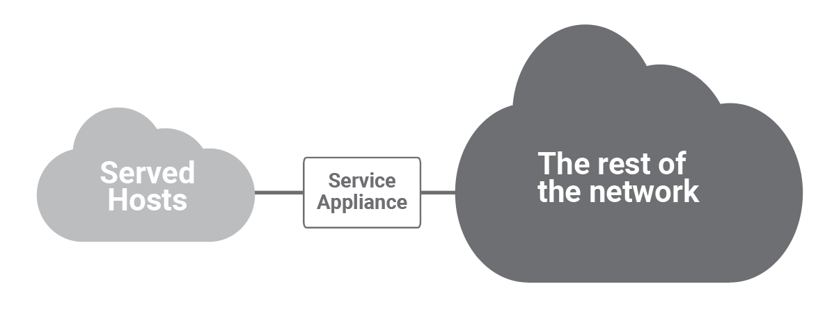
Network and security services have traditionally been deployed in front of a group of end hosts that share some common function and are topologically close: e.g., private corporate clients, public corporate servers, the servers of a specific department, the hosts of a corporate branch. The following figure shows a most common deployment model for services such as NAT, load balancers and firewalls.
With virtualization, while the same logical model still applies, the physical placement of the hosts, their physical proximity, and the natural point to deploy the service application (on the shortest path of traffic to and from the served hosts) have disappeared. Of course! It is in the very nature of virtualization (as well as its value and goal) to make all functional components (resources, topology, location) independent of the physical ones. Hosts communicating with each other can be anywhere in a data center and consequently the network design must:
- Provide equal and abundant bandwidth between any pair of hosts.
- Separate “physical” adjacency (in the IP terminology sense, namely layer two connectivity) from the actual physical topology.
The Clos network topology with its fractal capability of scaling (possibly incrementally) by adding identical components (leaf and spine switches) interconnected according to the same pattern, effectively solves the first requirement.
Network virtualization techniques, such as SDN (Software Defined Networking) and VXLAN (Virtual Extensible LAN), address the second requirement.
In this context, the remaining challenge is how to deploy the networking and security services (whether discrete/physical appliances or virtual network functions running on the same type of physical hosts as the workloads), in front of the (virtual) hosts they serve. The solution relies on the same technologies and infrastructure that make logical proximity independent of physical (topological) proximity: network virtualization.
Specifically, there are two main mechanisms that can be used for this purpose:
- Configure the service (virtual) appliance as the default gateway for a particular IP subnet. This requires layer two connectivity between the source of the traffic and the appliance. All packets that need to go outside the IP subnet need to cross the appliance/default gateway by definition.
- The appliance injects a default route using a routing protocol like BGP or OSPF. All traffic that does not have a more specific route to the destination will follow the default route and therefore traverse the appliance.
We will subsequently discuss more details and the implications of these two techniques when used in conjunction with Clos networks in data centers.
What is traffic tromboning?
Whichever of the above techniques is deployed, traffic between topologically close hosts might take a long detour and get back, as shown in the figure below.
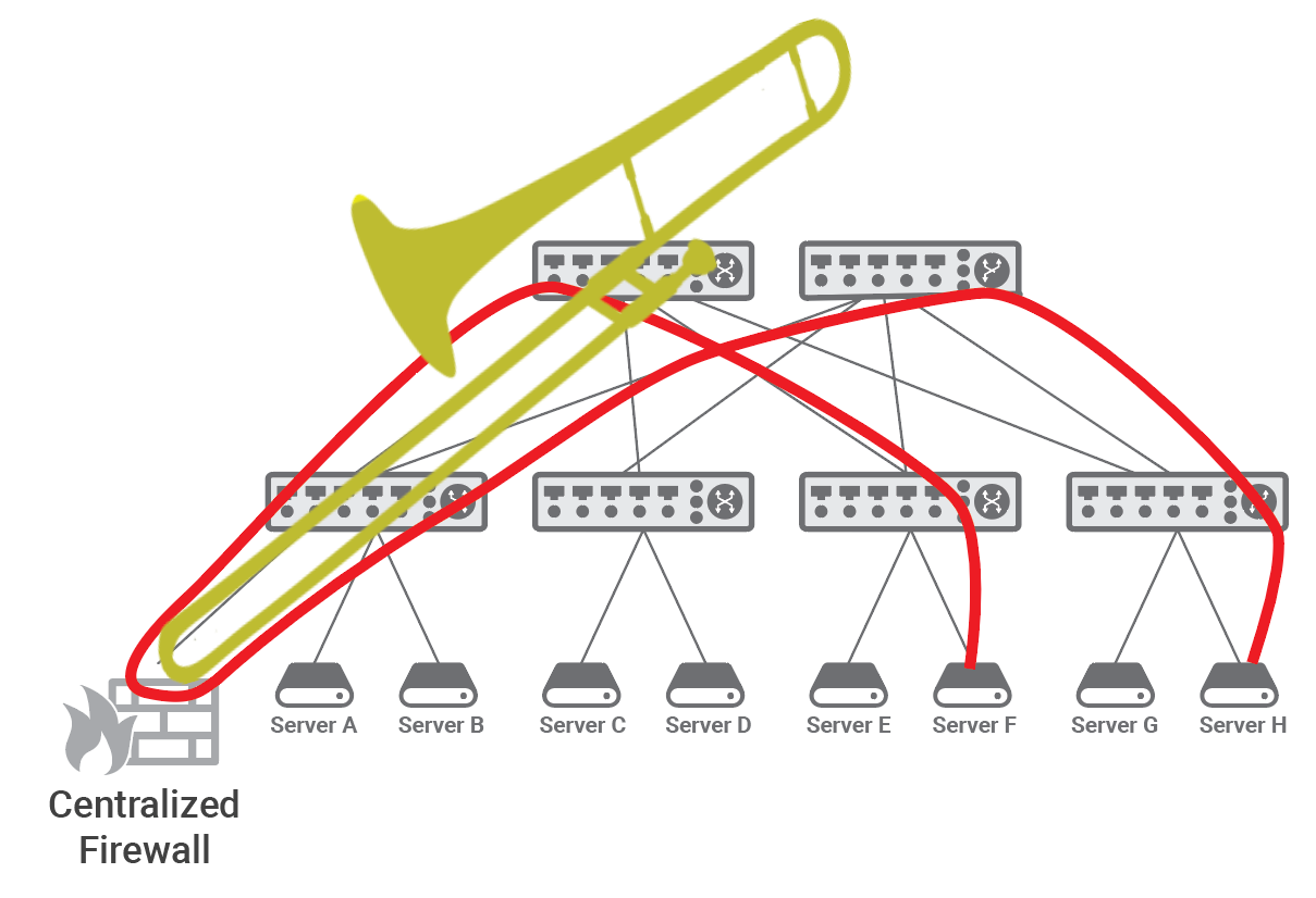
This phenomenon is commonly known as traffic trombone or traffic tromboning, as the shape of the path taken by the traffic in the network resembles the shape of the brass musical instrument that dates back to the 15th century and whose name, trombone, derives from “tromba,” the Italian word for trumpet: a large trumpet.
In a data center fabric based on a Clos topology, traffic tromboning results into traffic traversing the leaf-spine fabric twice, which leads to duplication of both network load and the latency experienced by the two hosts.
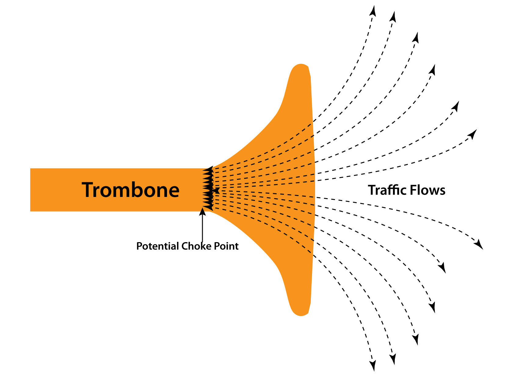
Moreover, when services are applied to traffic between most pairs of hosts, the appliance becomes a funneling point - also recalling the shape of a trombone - that must be traversed by traffic from a disparate set of source-destination pairs (see the following figure for a graphic representation). We will therefore subsequently refer to service appliances such as firewalls, IDSs (Intrusion Detection Systems), NAT (Network Address Translation), load balancers, as trombones.
Trombones, by their very nature, create a network traffic scalability problem. Addressing this through load balancing among multiple trombones is challenging since their services are often stateful.
Let’s consider a ubiquitous combination of a firewall and a NAT that we all have in the router that connects our house to the Internet. When a family member browses the Internet, a TCP session is created. The router needs to create a NAT rule for the outgoing traffic, but also a second one for the return traffic. These two rules need to be kept for the duration of the TCP session.
If, for example, in a corporate network context, two or more NAT appliances are required for scale or fault tolerance, one of the following should apply:
- Direct and reverse directions of a flow should go through the same appliance.
- State should be synchronized across the various appliances.
Synchronizing state across appliances is at best impractical and at worst impossible.
For example, if a NAT function is present, the packet on the Internet will have the NAT source IP address. If multiple appliances are deployed in parallel, the reverse traffic will be explicitly addressed and routed to the NAT instance with the IP address used for the translation. Hence, when a flow is assigned to a traffic trombone, it uses that particular trombone for all its duration or until the trombone fails.
Mechanisms exist for high availability across multiple trombones in case of catastrophic failures.
North-South vs East-West Traffic
Not every trombone is a bottleneck. Historically tromboning was happening towards the wide area network, a typical example being the firewall connecting a corporate network to the Internet. However, usually in that scenario the capacity of the link to the service provider is the bottleneck.
Today some high end firewalls, albeit costly, are capable of supporting up to 100 Gbps. Firewalls operating at 1 Gbps are very common and cheap, with 10 Gbps ones being considered the reasonably priced midrange. Therefore firewalls are typically not choke-points when used to connect to the Internet, a type of traffic that is also called North-South in a data center.
Different considerations apply to East-West traffic, i.e., the traffic inside the data center.
We have seen in a previous post that the amount of East-West traffic is at least ten times larger than the North-South one.
When applied to East-West traffic, the firewall trombone may become a bottleneck. In the same post, we have also discussed how placing the trombone on a Clos network disrupts optimal routing increasing latency and causing a large percentage of the network bandwidth to go wasted.
There are indeed enterprise deployments where this might not be a problem because the traffic is limited compared to the large capacity of the data center fabric and the specific applications utilized can tolerate latency. But, there are a significant number of cases where traffic tromboning drawbacks are critical, with obvious examples being cloud provider data centers (where the fabric bandwidth is shared by the various tenants) and market segments that deploy time sensitive applications, such as financial trading.
How is traffic tromboning realized?
Let’s now consider the configuration complexity of traffic tromboning for East-West traffic in conjunction with Clos networks for the two approaches previously mentioned.
Layer two traffic tromboning
To explain this first configuration we will reuse a figure from the previously mentioned post.
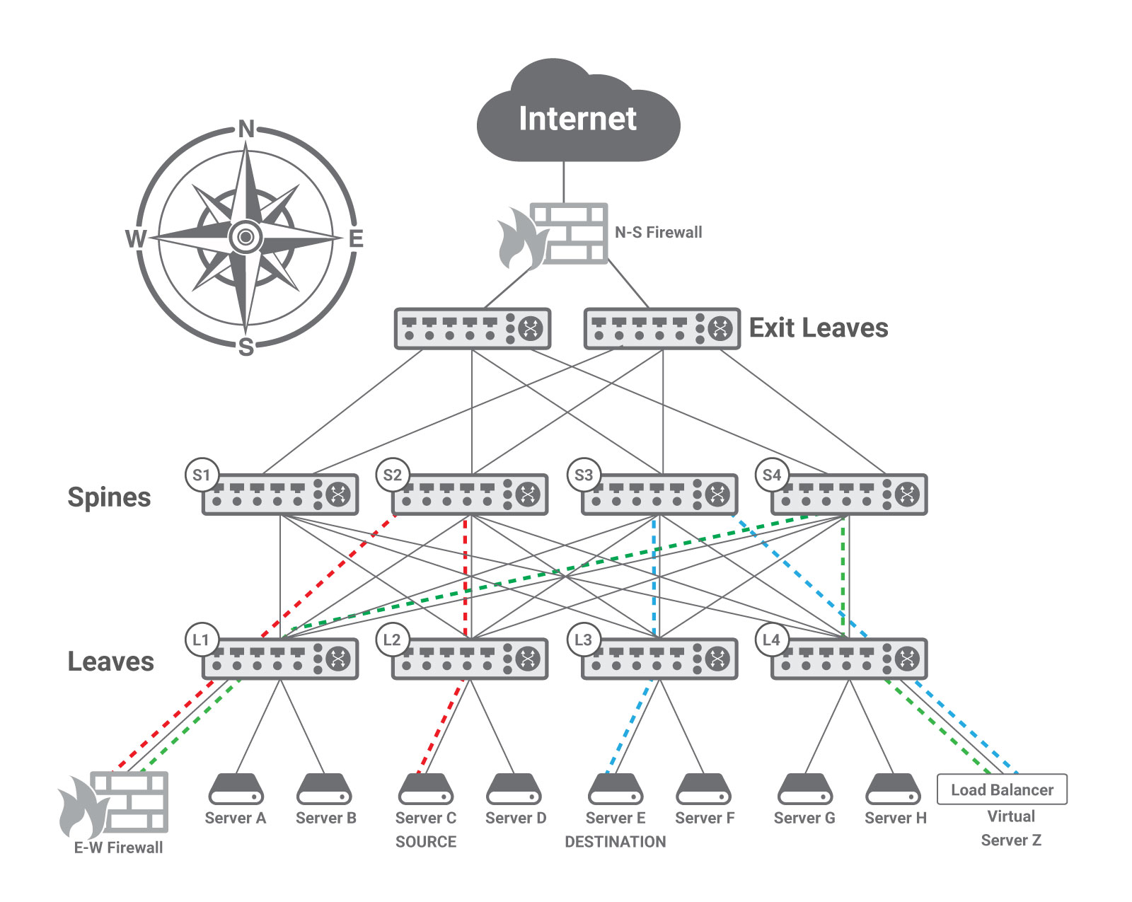
In this example, the E-W Firewall is deployed in transparent mode, acting as the default gateway for the server C subnet. As previously explained, IP rules require that a host and its default gateway be in the same subnet, i.e., be able to exchange layer two frames.
This requires some type of encapsulation, because in typical Clos data center networks each leaf implements a layer two domain (with its own IP subnet) and uses layer three forwarding towards the spines leveraging ECMP (equal cost multi-path) routing to spread the traffic across multiple paths. Therefore the network administrator needs to deploy an encapsulation technique, like VXLAN, to create a virtual layer two domain including server C (at leaf L2) and the E-W Firewall (that is physically connected to leaf L1).
Since the firewall needs to serve as a default gateway for servers connected to multiple leaves (namely, multiple IP subnets), VLAN trunking is typically enabled between leaf L1 and the E-W Firewall. Each VLAN contains the IP subnet of a leaf and is mapped to a VNID (Virtual Network IDentifier) of the VXLAN protocol. For example, the leaf L2 may encapsulate the native VLAN toward server C in a VXLAN tunnel with VNID = 88 and leaf L1 may remove the VXLAN encapsulation and map VNID = 88 to VLAN = 8 toward the E-W Firewall. Leaf L4 may use VNID = 44 and leaf L1 may map it to VLAN = 4. The same applies to the reverse direction.
This approach therefore uses a layer two network virtualization technique.
Layer three traffic tromboning
In order to use layer 3 routing to force traffic through a trombone, that trombone must inject a default route that is propagated through the network and used for all traffic that does not have a more specific route. With reference to the previous figure, a default route injected in the fabric by the E-W Firewall can be used to steer the traffic from Server C to Server Z through the firewall only if leaf L2 and the other leaf and spine switches involved do not have a more specific route to Server Z. How can this be possible, while enabling Server Z to be reached by packets once they have been processed by the firewall?
The solution is offered by layer three network virtualization. Virtual Routing and Forwarding (VRF) is a popular technique allowing multiple instances of a routing table to exist in a router and work simultaneously. Each physical interface (i.e., a port) or logical interface (i.e., a VLAN) is associated with one VRF instance. The BGP routing protocol is deployed to advertise routes specifying the VRF instance they belong to.
In the specific case of the above figure, the East-West traffic requires three VRFs: red, green, and blue. The E-W Firewall is the only point of contact in the red VRF between Server C and the rest of the network, and thus all the traffic must transit through the firewall. To achieve this the E-W Firewall injects a default route into the red VRF that is propagated through the network and used for traffic on the red VRF. The routing tables of the red VRF contain more specific routes only to destinations connected to leaf L2, including Server C; consequently, when switches route a packet addressed to Server Z, they send it towards the firewall as indicated by the default route.
The E-W Firewall is deployed in routed mode and participates in two VRFs: the red VRF associated with the IP subnet of Server C and the green VRF associated with the load balancer (i.e., Server Z). The firewall’s routing table includes a route to Server Z through the physical or logical interface that belongs to the green VRF; hence, the packet is forwarded back into the fabric through such interface. Leaf and spine switches apply the green VRF whose tables contain a specific route for Server Z.
The load balancer executes its function and determines that the packet should be delivered to physical Server E. The load balancer’s routing table has a route to the IP subnet of leaf L3 through the interface associated with the blue VRF. Hence, once the load balancer forwards the packet into the fabric, switches use the blue VRF tables that contain a route to the subnet of Server E.
The trombones can be connected to multiple VRFs either using multiple physical ports or multiple logical interfaces (e.g., VLANs) on the same physical port, and do not need to be VRF-aware. They just need a single routing table with routes through the proper physical or logical interfaces. In our use case, the E-W Firewall learns such routes by maintaining two routing sessions (e.g., using BGP): one on the red port (physical or logical) and the other one on the green port.
All the spine switches in our network participate in the three VRFs. Leaf L1 is part of the red and green VRFs, leaf L4 green and blue, leaf L2 red, and leaf L3 blue. More VRFs can be deployed on leaves to serve the remaining hosts.
In this case the use of VXLAN is not needed and is replaced by VRF. More complicated schemes that combine VXLAN and VRF are also possible.
How to avoid traffic tromboning
This analysis of traffic tromboning leads to very similar conclusions to the ones of our previous post. Whenever possible, centralized appliances should be avoided for East-West traffic since they are bottlenecks, disrupt optimal routing, and introduce significant latency and jitter. Instead, the same scale out model utilized for the compute should be leveraged by naturally placing services in a distributed fashion at the edge.
In virtualized and containerized environments, this can be achieved by executing services in a Virtual Machine (VM) or container running on the very host where workloads receiving the services are executed. This approach still results in a small tromboning effect within hosts (as traffic flows between workloads and service VM) or between neighboring hosts if service VMs are not placed in every single host.
Such local tromboning can be avoided by including services in the hypervisor software stack, for example within the virtual switch.
Both above solutions cannot be applied to bare metal (not virtualized and containerized) environments and share the major drawback of taking CPU and memory resources away from paying workloads to implement services.
Hence, the best solution is having specialized hardware on the hosts to implement and run services. The ideal point to place such hardware is at the network attachment that is naturally on the traffic path.
Adopting domain-specific hardware for services at the edge and installing it in conjunction with servers allows services to:
- run at wire speed without taking away any resources from the workloads executing on the hosts
- scale at the same rate as compute.
Further Reading
Gur Shatz, Is your network suffering from the trombone effect?
Andy Gottlieb, Why the ‘trombone’ effect is problematic for Enterprise Internet access
Ivan Pepelnjak, Traffic Trombone (what it is and how you get them)
My book has a description of some of these topics in Section 2.7.
You can read an independent review of the book here.
The book was also listed in The Top 10 Best Cloud Storage Books You Need to Read in 2020.
Don’t Forget that Pearson/Addison-Wesley has a special offer on my latest book. To save 35% on the book or eBook go to the informit website and use code FUTUREPROOF during checkout to apply the discount. Offer expires December 31, 2020